Direct Modeling

At long last, it’s time to write about advanced CAD techniques. I’m going to preface this article with a disclaimer that different people/teams/companies have different preferences with regards to CAD organization and flow, and different projects may have different needs in terms of revision, so one technique may not fit all applications. That said, you should definitely be aware of what’s out there. Be warned that it may drastically improve your life.

We are initially taught CAD through a “historical” context. This doesn’t mean we need to learn the history of CAD, it just means that we are taught to build parts via a chronological history often structured in a tree. For example, first, you make a sketch, then you extrude the sketch, then you add a couple of holes to the extrusion, and then some fillets, etc. This works extremely well for simple parts, but once you go back and make edits to things in the tree, anything and everything breaks (I’m talking to you Solidworks).

We absolutly love using Onshape for our CAD examples!


The Intro

Lucky for us, there are other ways to model! Often, these require you to have a deeper understanding of how CAD works and what you are making.

In one style (parametric modeling) You need to see into the future and note what you expect to change, defining and referencing features accordingly. Variables/planes/points are defined very early on and everything is based on them.

Or, you can ignore all history and treat each individual body as a fresh slab of marble ready to carve up via pushes, pulls, face moves, and face deletions. We call this direct modeling.

At larger companies where many engineers are involved in a big assembly, there is “in place” modeling where no assembly constraints are ever used and everything is modeled in context. What exists around your part defines how your part is modeled (non associatively please).

Another form of modeling that can be combined with the techniques above is boolean modeling. You never cut away directly with extrusions, instead, all features are bodies and you unite, subtract, or intersect them together to form your part! This is a very popular form of modeling among CAD veterans.

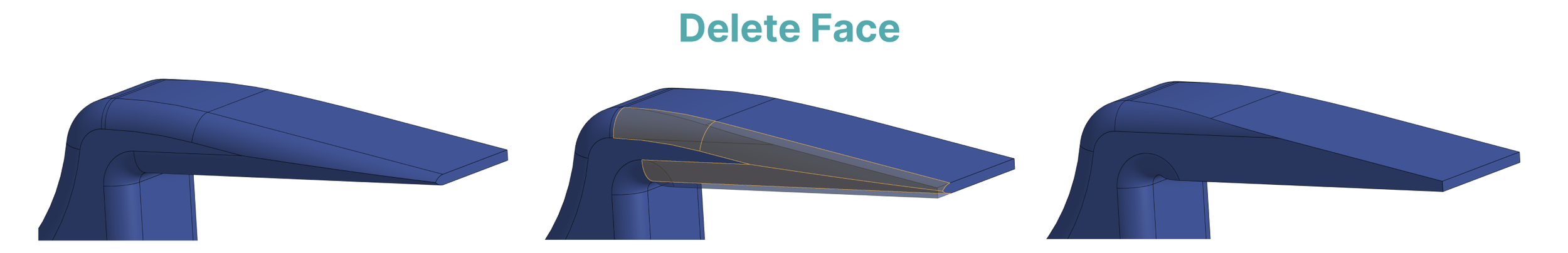
Today we are going to talk about a personal favorite, direct modeling! I still remember the feeling of awe when I first discovered what was possible here (and the subsequent feelings of frustration whenever it didn’t function perfectly). Direct modeling is the foil of sketch-based modeling, and primarily uses 3 functions: move/offset face, delete face, and replace face.


Move Face

Extrude can’t always get the job done (at least not easily). For instance, let’s say that you’ve been tasked with making a towel rack for the oven, and after printing the first iteration, you decide that you want the fins to the right to extend further. You could either go back into the feature tree (which is a mess unless you are one of the 1% of people who label their features), or you can move face.

Note that extruding would produce a profoundly ugly and unintended result. You don’t want to scroll back in the feature tree before the correct fillet and extrude from there to avoid jagged edges, or refillet after for a sloppy look. Not to mention that both the top and bottom protrusions are tapered, and an extrusion will merely take a face and extend it without regard for the surrounding geometry. We want to leave the face tapered without messing around with further chamfering/drafting afterwards.

So we apply the beautiful, stunning even, move face! Look at how it transfers the fillet locations and preserves angle. This is especially ideal for scenarios in which we want to CAD “quick and dirty,” particularly because it will likely cause problems if you later try to edit an earlier feature in your feature tree. For this reason, older engineers are typically not a fan of this technique (and it is thusly rarely taught in school, particularly due to lack of effective direct modeling features in Solidworks). This is why we use Onshape (direct modeling works super well!). They will say it clogs the feature tree and makes part transfer significantly more difficult. They’re right of course, but in our opinion, the benefits outweigh the drawbacks.

Early on in my engineering career, I was totally overwhelmed when receiving a part with 1000 unlabeled actions in the feature tree, and struggled to make adjustments without breaking the part. To combat this issue, a popular technique is to merely copy over the geometry into the released part, abstracting away any and all features, essentially forcing anyone receiving the part during a transfer to CAD the part from scratch (also known as the “dumb CAD”), construct tools and boolean unite/subtract features (an entirely separate technique with many merits), or simply use direct modeling.


Delete Face

Let’s say I want to get rid of the fillets on the top protrusion because the print keeps failing (ask me how I found out). I don’t want to get rid of all the fillets or go into the feature tree to find it, so instead I can just “delete face” the fillets i want to remove! This is significantly faster, easier and lower effort than any other method, and can be incredibly useful, not just for deleting fillets, but other faces and geometry as well. Delete face and move face probably represent about 60% of my CAD operations on a given day. Note that delete face has its limits, and not all situations will work well for it (though depending on the CAD program you use, it is remarkably powerful → especially Onshape). Imagine a non-regular curved surface with a triangular prism cut out of it. Without surfacing, there is no effective way to match the curvature of the surface without knowledge of its definition or delete face.

The way that delete face works is that it tries to stitch together adjacent [unselected] faces. It frequently relies or previous geometry in that location, or matching curvature/edges. Sometimes, when stitching those faces back together, the CAD program will change the geometrical definition of the face. There are various mathematical formats that are used in CAD to express geometric faces, but imagine representing a rectangle as a set of 4 points, vs. representing that same rectangle as set of 10,000 points because one of the corners is 0.00000001 mm out of plane with the others. As you can imagine, this misrepresentation becomes much more likely with synchronous modeling tools and is another reason there are many detractors. A heavier weight mathematical representation can cost compute, loading time, and modeling time, ultimately resulting in a higher cost than the upfront cost of building using simpler operations. All that said, I am still a huge fan of the operation and use it very frequently. There are ways to “optimize geometry” later on if this causes issues.


Replace Face

Replace face: The least used of the three, replace face essentially acts as move/offset face but up to a certain entity (usually a face). Instead of fiddling around with settings or measuring distances, only two clicks are required: the face to move (target), and the face to make it in plane with! Take the example below: say we want to close the gap between the two protrusions, and try using move face. As you can see, it sort of works, but fails to match the angle of the plane we want to intersect with. As such, there’s a bit of a discontinuity. Replace face fixes the issue immediately and without complications. Of course, you could also make a sketch, project lots of dimensions and extrude, but 2 clicks is better than 100 clicks in most cases.

Ok, so now you know the fundamentals of direct modeling. It’s time to answer the big question: Why is it Illegal?

First off, as we mentioned earlier, in a lot of workplaces, the stigma around using “delete face” or “move face” in a feature tree or completely deleting the history of a model can make it seem like a hacky/non-professional approach to CAD. It’s very freeform, and even if history is left on, it will become indecipherable after using hundreds of these operations. As such. some people like to CAD admin, Co-workers, or managers might get frustrated with it. In most cases, WE DISAGREE. Unless the part is extremely well defined, and frequent minor tolerances updates & incremental changes are the only ones left to be made, strictly parametric modeling is not well justified. Associativity and feature mapping are too reliant on geometrical features rather than design intent, and that doesn’t seem likely to change any time soon.

The other reason this is illegal, is that it’s forbidden knowledge. Schools do not tend to teach this as a strategy (mostly because it’s the CAD admin type of person who teaches a CAD class) despite it being criminally effective for speeding up CAD workflows on the majority of projects, especially in Onshape or NX.